


Unsuppressed LED drivers are a common source of vehicle radio interference, and yes, the static you’re hearing is probably coming from your lights, not your radio. Isolate the suspect lamp, check ground continuity at the fixture and chassis, then clip on a ferrite choke as a diagnostic test. If that quiets the noise, you’re looking at either a proper filtering fix or a swap to a CISPR 25 Class 4–5 luminaire for the permanent repair.
TL;DR:
- Ferrite chokes near the driver can quickly reduce radio static if interference is caused by conducted emissions.
- Identifying whether noise is from radiated or conducted emissions helps determine if routing, grounding, or filtering fixes are most effective.
- Interference mainly stems from switching noise in LED drivers, especially in low-frequency bands like AM, where harmonics are strongest.
- Proper testing includes tuning affected bands, activating features individually, and checking wiring proximity to locate the interference source precisely.
- Using LED fixtures certified to CISPR 25 Class 4–5 and verified through specific testing methods minimizes the risk of radio interference.
What causes led light radio interference in vehicles?
LED interference reaches your radio through two separate paths, and knowing which one you’re dealing with changes the fix entirely. Conducted emissions travel along the power wiring itself, back through the vehicle’s DC bus, into whatever else shares that circuit. Radiated emissions leave the wiring and housing directly, the way a poorly shielded antenna would, and show up regardless of whether anything is electrically connected.
Both trace back to the same root cause: switching. Most LED drivers regulate brightness with pulse-width modulation (PWM) or a switching buck converter, chopping DC voltage on and off thousands of times per second to control current, as explained in detail in Empowering Manufacturers with EV Charging | Swift Charging. Every transition edge generates a sharp voltage spike, and those spikes contain harmonic energy that spreads across a wide frequency range, well into the bands your radio equipment listens on.
Parasitic capacitance inside the driver and between the wiring and vehicle chassis gives that switching noise a path to ride out on. Long harness runs, especially unshielded ones near the antenna cable, can act like unintentional antennas and radiate the noise directly. Multi-function light bars and beacons tend to be worse offenders than a single fixed-output lamp because they typically pack more switching circuitry, more drivers, and more wiring into a compact space.
The bands affected most:
- AM broadcast — highly susceptible because it operates at the low frequencies where switching harmonics are strongest.
- SSB and amateur HF radios — sensitive receivers with narrow filtering pick up conducted noise readily.
- VHF/UHF land mobile and public safety radios — less affected by low-frequency harmonics but vulnerable to radiated noise from poorly routed harnesses.
- GPS and cellular — occasionally affected when harmonics land on specific channels, though this is less common than AM/HF disruption.
Measured conducted emissions vary widely between LED lamps, and plenty of units that clear basic limits still generate enough radio frequency interference LED noise to disturb a sensitive AM or SSB receiver in the cab.
How do you find the noisy component?
You don’t need a chamber to isolate the source. A methodical bench and field sequence will get you there in under twenty minutes on most vehicles.
- Tune the affected band first. Set the radio to the frequency where you’re hearing the noise, ideally somewhere quiet with no station, so the interference is obvious against the noise floor.
- Run the turn-on correlation test. With the engine running and radio tuned, activate each lighting function one at a time, not all at once. Note exactly which function introduces the static: strobe pattern, steady burn, or a specific flash mode.
- Do a proximity sweep with a portable radio. Walk a battery-powered AM/FM or handheld radio along the harness and around the fixture housing itself. If the noise gets louder near the wiring but doesn’t change near the lamp head, you’re dealing with radiated emissions from the cable, not the driver.
- Inspect wiring routing. Look for harness runs that parallel or cross the antenna cable, especially within a few centimetres. Proximity matters more than most technicians expect.
- Check and rework grounds. A loose, corroded, or long ground return is one of the most common contributors to conducted noise. Verify continuity from the fixture chassis to a clean, short path back to vehicle ground.
- Log everything before calling the supplier. Record which function triggers it, whether it tracks with engine RPM or dimmer position, and what band or frequency is affected. That detail saves a technical support call from turning into a guessing exercise.
Pro Tip: Keep a cheap analog AM radio in the toolbox. Digital receivers often mask or digitally filter low-level interference that an old-fashioned AM tuner will expose immediately, making it a faster diagnostic tool than your factory unit.
If the noise correlates with dimmer position rather than just on/off state, that’s a strong signal the driver’s PWM frequency itself is the culprit, not the wiring.
Which fixes actually stop LED radio noise?
Not every fix belongs in every situation. Some are five-minute field patches; others require pulling the fixture and rewiring. The table below breaks down where each mitigation applies and how long it holds.
Ferrite chokes are the fastest diagnostic and often the fastest fix. Clip one around the power cable as close to the driver as physically possible, and if space allows, loop the cable through the core two or three times before clamping. More turns through the core generally increase suppression, though returns diminish past three or four loops. Mn-Zn ferrite material handles lower frequencies more effectively, which suits AM and lower HF interference, while Ni-Zn material performs better at higher frequencies, useful for VHF-range noise. If a snap-on choke resolves the static during your field test, that tells you the noise is conducted and gives you a strong case for a permanent inline filter rather than a full driver swap.
Inline EMI filters belong on the input side of the driver, between the vehicle’s power feed and the driver itself, where they intercept conducted noise before it enters the circuit that’s radiating it. Some filter designs also use Y-capacitors bridging the line to chassis ground, but that grounding path needs to be genuinely low-resistance or the filter’s effectiveness drops sharply. Peer-reviewed testing on DC-DC buck converter LED lights found that a properly implemented EMI filter and common-mode choke brought a noisy converter into CISPR 25 Class 5 compliance under lab conditions, which is a meaningful data point if you’re deciding whether filtering alone can solve a stubborn case.
Wiring and grounding work costs nothing in parts and often delivers the biggest improvement per hour of labour. Twisting the driver’s output pair reduces the loop area that radiates noise, and running a short, low-resistance ground return from the fixture chassis directly to the vehicle body, rather than daisy-chaining through another accessory’s ground point, cuts common-mode radiation without touching the driver at all.
Housing shielding matters when the fixture itself, not just the wiring, is radiating. A metal housing with proper bonding to chassis ground contains emissions that a plastic or poorly grounded metal housing lets escape.
Pro Tip: If you’ve fitted a ferrite choke, reworked the ground, and twisted the output pair and the radio is still noisy, stop chasing field fixes. That combination covers the practical limits of retrofit mitigation, and the remaining option is replacing the fixture with a certified low-emission unit.
When a fixture demands filter after filter and still bleeds into the radio, that’s your signal to move from patching to replacing it with hardware engineered for low interference from the start.
What do CISPR 25 and EN 55015 actually certify?
CISPR 25 governs radio disturbance from vehicle electronics across 150 kHz to 5.925 MHz and defines five emission classes. Class 4 and Class 5 luminaires carry the tightest limits, engineered specifically to avoid interfering with on-board radios and GPS receivers, which is the class range worth asking about when you’re specifying lighting for a fleet with sensitive communications equipment.
EN IEC 55015 covers the 9 kHz to 1 GHz range and permits two different test methods: SAC (semianechoic chamber) and CDNE. CDNE is faster and suits production quality control, but its results aren’t strictly equivalent to a full SAC chamber test, which remains the more exhaustive method for resolving disputed cases.
Before taking a vendor’s EMC claim at face value, verify:
- Which specific class rating (1 through 5) the component test actually claims, not a vague “CISPR 25 compliant” label.
- Whether the test was conducted at the component level or the system level, since a driver tested alone with a resistive load can behave differently once it’s wired into a real housing with parasitic capacitance and harness routing.
- Which method, SAC or CDNE, produced the certificate, particularly if you’re troubleshooting a borderline case.
How Strobe My Ride supports technicians working through LED interference
Strobe My Ride is a Canadian-owned supplier of LED warning lights, work lights, and vehicle-lighting accessories, stocked in Ottawa and shipped across Canada to tow and roadside operators, snow-removal and construction fleets, municipalities, volunteer fire departments, funeral homes, and commercial vehicle operators.
The Strobe My Ride catalogue spans light bars, mini light bars, beacons, surface mounts, hideaways, dash and deck lights, work and scene lights, traffic advisors, and OEM flash modules. Specifications and certifications vary by individual SKU and jurisdiction, so once you’ve isolated a noisy fixture using the diagnostic steps above, bring your notes, which frequency band, which function, whether the noise tracks with dimming, to the product page or to Strobe My Ride’s technical support team so they can point you toward SKU-specific EMC information rather than a generic answer.
What are the rules around LED radio interference by region?
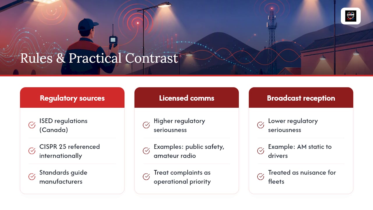
Vehicle electronics in Canada fall under Innovation, Science and Economic Development Canada’s (ISED) radio equipment regulations, which govern interference from electronic devices generally, while emissions testing standards like CISPR 25 are referenced internationally as the technical benchmark manufacturers design against. Enforcement mechanisms and penalty structures differ by jurisdiction and by whether the interference affects licensed spectrum, such as amateur radio or public safety communications, versus general broadcast reception.
For fleet operators and technicians, the practical takeaway isn’t memorizing penalty schedules; it’s recognizing that interference with licensed communications, particularly public safety or amateur radio bands, carries a different level of regulatory seriousness than a driver annoyed by AM static on a road trip. If your fleet operates alongside two-way radios, GPS tracking, or any licensed communications equipment, treat interference complaints as an operational priority rather than a nuisance, because it can point to hardware that doesn’t meet the class rating your application actually needs.
Strobe My Ride does not provide legal, regulatory, or compliance advice on interference rules for your specific jurisdiction or vehicle class. If you need to confirm regulatory obligations tied to your fleet or region, consult the relevant regulatory authority directly, and use the diagnostic and mitigation steps in this guide to address the technical side while you do.
Does LED interference get worse over time?
Interference that starts as a faint tick on the AM band rarely stays faint. Connectors loosen, ground straps corrode, and wiring insulation chafes against brackets over months of vibration and thermal cycling, and every one of those failure modes tends to increase both conducted and radiated emissions rather than reduce them.
The practical cost shows up gradually. A dispatcher who has to repeat radio calls twice as often because of background static is losing time on every transmission. A driver who stops trusting their AM traffic reports because of constant crackle stops using them altogether, which defeats the purpose of having the radio at all. In amateur or public safety contexts, degraded signal quality can mean missed transmissions at exactly the moment clear communication matters most.
There’s also a compounding effect specific to fleets: if one fixture on a vehicle is radiating noise into the harness, and a second accessory later gets wired into a nearby ground point, the interference can worsen even though nothing changed on the original light. That’s why the grounding and routing checks in the diagnostic section aren’t a one-time task. They’re worth repeating whenever new equipment gets added to a vehicle, not just when someone first complains about noise.
What do real-world interference cases look like?
A tow operator reports static on the CB every time the rear scene lights kick on at full brightness, but not at reduced output. That dimmer-correlated symptom points straight at the PWM driver, since interference tied to brightness level rather than simple on/off state is a strong tell that switching frequency is the source, not a wiring fault.
A municipal fleet notices interference only when a specific beacon is mounted near the roof-mounted antenna base, but the identical beacon model on a different vehicle, mounted farther from the antenna, causes no complaints. That’s a radiated emissions case driven by physical proximity, not a defective unit, and the fix is antenna separation or wiring reroute rather than a warranty claim.
A volunteer fire department’s portable radios work fine at the station but crackle badly near the truck’s light bar when the engine is running and the alternator is under load. Engine-RPM correlation like this often points to a shared or marginal ground path that gets noisier under electrical load, rather than the light bar’s driver itself. Rework the ground return first, before assuming the fixture needs replacing.
Each scenario traces back to the same diagnostic principle: correlate the noise with a specific trigger, whether it’s brightness, proximity, or engine state, and that correlation tells you which fix category to start with.
How do you measure LED interference precisely?
Field tests with a portable radio and a ferrite choke get you most of the way to a diagnosis, but quantifying interference precisely for a warranty dispute or a fleet-wide specification decision calls for more rigorous tools.
A spectrum analyzer with a near-field probe lets you scan the frequency range directly at the harness or driver and see exactly which frequencies carry the strongest emissions, rather than relying on your ear against a noise floor. Conducted emissions testing using a line impedance stabilization network (LISN) measures noise on the power line itself under controlled conditions, closer to what a certification lab would use, and separates conducted noise cleanly from anything radiating through the air.
For radiated emissions, chamber-based SAC testing remains the most exhaustive method, while CDNE offers a faster, less expensive alternative suited to production QC rather than dispute resolution, a distinction worth remembering if a vendor hands you a CDNE-only certificate for a component you suspect is marginal. None of this equipment is standard technician kit, but knowing it exists, and knowing which lab methodology backs a given certificate, changes how much weight you put on a spec sheet versus your own field results.
Get low-interference lighting and support from Strobe My Ride
Chasing ferrite chokes and ground straps has its limits, and once you’ve confirmed a fixture is the source, the fastest path forward is swapping in hardware built with interference control in mind from the start. Strobe My Ride stocks its lighting inventory in Ottawa and ships across Canada, so replacement units reach fleet technicians faster than waiting on cross-border freight, with real people on the phone if you need setup help rather than an automated ticket queue.
If you’re specifying a replacement search or scene light after tracing interference to a driver, check the Fleet Search high-output LED search light product page for SKU-specific EMC details before ordering. For beacon-class applications, the Signal Beacon-Lite 360 is worth reviewing on its own product page, and for work-light housings, the Signal Arc work light page lists its own SKU-level specifications.
Bring the diagnostic notes you collected, which function, which band, whether it tracks with dimming or engine load, when you reach out to Strobe My Ride’s technical support team, since that detail lets them point you to the right SKU rather than guessing. Specifications, certifications, and EMC claims vary by individual product, so always verify against the specific product page, or browse the full Strobe My Ride catalogue to compare fixture types side by side.
FAQ
How do I stop my LED lights from interfering with my radio?
Isolate the fixture causing the noise, check the ground connection at the light and chassis, and test with a snap-on ferrite choke placed close to the driver. If the choke reduces the static, a permanent inline EMI filter or a rewired, twisted output pair usually finishes the job.
Do LED lights cause electrical interference?
Yes, LED drivers that use PWM or buck-converter switching generate voltage spikes that create both conducted and radiated interference. Measured testing shows emissions vary widely between LED products, so not every LED light causes the same level of disruption.
How do I get rid of radio interference from vehicle lighting?
Start with the turn-on correlation test to identify the exact function causing noise, then work through grounding, ferrite chokes, and wiring reroutes before considering a driver or fixture replacement. Fixtures rated to CISPR 25 Class 4 or 5 are engineered specifically to minimize this kind of disruption.
What are the best ferrite chokes for LED lights?
There’s no single “best” choke since material and sizing depend on the frequency band you’re suppressing. Mn-Zn ferrite cores generally handle lower frequencies like AM and HF better, while Ni-Zn cores perform better at higher VHF frequencies, and looping the cable through the core two or three times typically improves suppression over a single pass.
Where can I find low-interference LED lighting for my fleet?
LED lighting is available across various product lines, with SKU-specific EMC information available on individual product pages. Contact the technical support team with your diagnostic notes to identify a fixture suited to interference-sensitive applications.


