


The safe pattern is simple: a fused main feed runs from the battery or fuse block to the panel’s power input, then each switch sends its own fused or relay‑controlled output to a single device, and every circuit shares a common ground return to the negative bus. Disconnect the battery before you touch a single wire. Get the mental model right before you pick up a crimper, because most DIY failures trace back to one of three habits.
- No fuse or breaker within roughly 7 inches of the power source.
- Wire gauge chosen by guesswork instead of amp draw and round‑trip run length
- Heavy loads (compressors, pumps, driving lights) wired straight through a switch instead of through a relay
Key Takeaways
A safe 12V switch panel install depends on near‑source fuse protection, correctly sized wire for the round‑trip run, relays on high‑draw circuits, and a clean common ground.
| Point | Details |
|---|---|
| Fuse near the source | Protect the main positive feed within about 7 inches of the battery, per ABYC E‑11 guidance. |
| Size wire by round‑trip length | Measure there and back, then check the gauge against the 3% voltage‑drop guideline. |
| Use relays for heavy loads | Let the switch trigger the relay coil while the fused feed powers the device directly. |
| Ground everything to one bus | A single clean ground point is easier to test and less prone to hidden voltage drop. |
| Match switch to the job | The Patrol Switch is built specifically for wiring emergency light circuits into a panel. |
Primary sources and recommended further reading
- ABYC E‑11 electrical standards: overcurrent protection placement and panelboard definitions.
- NMMA / ABYC wire sizing and voltage‑drop guidance: the 3% rule and AWG reference ranges.
- MarinePowerLab’s switch panel wiring walkthrough: tools, crimping, and testing steps.
- Overland Equipped’s auxiliary power planning guide: accessory tallying and fuse block selection.
Component roles: panel, fuse block, relays, ground bus, and connectors
A switch panel has three distinct electrical jobs, and mixing them up is where a lot of home wiring jobs go sideways. The panel’s power input is the single feed that keeps every switch alive. Panel outputs are the individual wires leaving each switch toward a device. A separate illumination or backlight feed, where the panel has one, runs independently so switch lighting doesn’t share a circuit with the load itself.
- Fuse block vs. inline fuses: a fuse block centralizes protection for multiple circuits and keeps the wiring tidy; inline fuses work fine for one‑off additions but multiply clutter fast.
- Main master breaker: a single resettable breaker at the battery can back up individual fuses without replacing the near‑source protection rule.
- Relays: the coil side connects to the switch (low current), while the load side carries full power directly from the fuse block to the device.
- Negative bus and chassis ground: every circuit needs a short, clean return path, ideally to a common bus rather than scattered chassis points.
- Connectors: marine or vehicle‑grade tinned, stranded wire and sealed terminals resist vibration and moisture far better than bare household‑grade parts.
How do you wire a switch panel step by step?
Wiring a control panel properly comes down to five phases: plan, route, connect, protect, and test. Skipping the planning phase is the single fastest way to end up re‑running wire a second time.
- Plan the circuit. List every accessory the panel will control, then measure the round‑trip distance from the battery to each device and back. Add up the total amp draw and build in headroom. This is the same tally‑and‑measure approach Overland Equipped recommends before cutting any wire.
- Route the wiring. Follow existing harness paths where possible, keep runs away from heat sources and moving parts, and support the wire every 30 to 45 centimetres with clips or ties. Leave a small service loop at the panel and at each device so a future repair doesn’t mean pulling the whole run.
- Land the power feed and fuse. The main positive wire needs its fuse or breaker within about 7 inches of the battery or power source, a rule pulled directly from ABYC E‑11 electrical standards, which call for overcurrent protection right at the source on panelboards.
- Wire each switch output. Low‑draw devices, such as a single LED work light, can run directly off the switch. Anything pulling more current than the switch is rated for, like an air compressor or a winch accessory, should run through a relay instead, with the switch only triggering the relay’s coil.
- Complete the ground return. Bring every negative wire back to a common ground bus rather than a handful of separate chassis screws. A single, clean ground point is easier to troubleshoot later and reduces the chance of a stray voltage drop hiding in a corroded bolt.
- Test before you close anything up. Use a multimeter to check for continuity, confirm the fuse ratings match the wire gauge, then load each circuit and measure voltage drop at the device. A properly sized run should hold within the 3% guideline covered below.
Pro Tip: Label both ends of every wire as you route it, not after. It takes an extra thirty seconds per run and saves an hour of tracing wires behind a dash months later when you add a new accessory.
Wiring diagrams for common switch panel setups
A single SPST (single‑pole, single‑throw) switch wired for one accessory is the simplest layout: fused positive in, switch, fused or relay‑controlled positive out to the device, and a ground wire back to the bus. That’s the building block for everything else.
A multi‑switch panel repeats that block per switch, but all of them draw from one fused main feed and share the same ground bus, with each output still carrying its own individual fuse sized to that circuit’s wire gauge. A relay‑controlled high‑draw circuit adds one more stage: the switch output goes to the relay’s coil terminals (typically marked 85 and 86), while the relay’s load side (30 and 87) connects the fused battery feed straight to the device.
- Label terminals by function (power in, switch out, ground), not just by number, so a repair doesn’t require rechecking the whole diagram.
- Lights, compressors, and pumps behave differently under load. Lights draw a steady current, while compressors and pumps spike on startup, which is exactly the kind of load that belongs on a relay rather than direct through a switch.
How to size wire and keep voltage drop under control
Wire gauge should be chosen from the round‑trip distance, meaning the wire’s length from the battery to the device and back, not the one‑way distance most people measure first. Sizing by one‑way length is a common mistake that leaves circuits undersized on longer runs.
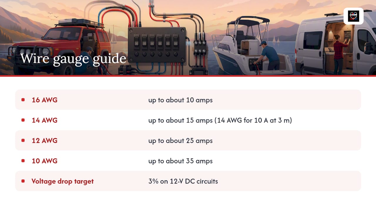
Industry guidance calls for keeping voltage drop to 3% on 12‑volt DC circuits, a threshold referenced in NMMA and ABYC wiring guidance. Stay inside that number and your lights run at full brightness and your pumps run at full speed; go beyond it and accessories start underperforming even though the fuse never blows.
As a practical reference point, that same guidance uses 16 AWG for loads up to about 10 amps, 14 AWG up to about 15 amps, 12 AWG up to about 25 amps, and 10 AWG up to about 35 amps, always checked against total round‑trip length rather than amp draw alone. A 10‑amp load with a 3‑metre round trip, for example, typically requires 14 AWG wire to minimize voltage drop. Undersized wire doesn’t just underperform. It heats up under load, which is a fire risk as much as an efficiency problem, so when in doubt, size up one gauge rather than down.
Relays, fuse placement, and conductor protection rules
Wiring a relay properly means keeping the switch and load paths separate: the switch’s output lands on the relay’s coil terminals, while a fused feed straight from the battery or fuse block powers the load side directly to the device. The switch never carries the device’s full current, which is exactly why relays exist for anything beyond a light‑duty accessory.
Fuse or breaker placement matters as much as the fuse rating itself. Transport Canada’s guidance on overcurrent protection flags missing near‑source protection as one of the most frequent compliance gaps in DIY electrical work, and the fix is straightforward: fuse the positive feed within a short distance of the battery, every time.
- The fuse protects the wire, not just the device, so size it to the conductor’s ampacity first and the accessory’s draw second.
- A fused distribution block lets you add circuits later without splicing into an already‑crowded feed.
Pro Tip: If you’re not sure whether an accessory needs a relay, check its rated draw against the switch’s amp rating. If the accessory’s number is anywhere close to the switch’s limit, wire it through a relay instead of pushing your luck.
Tools and materials checklist for a reliable install
A short shopping list before you start saves multiple trips back to the parts counter.
- Tools: multimeter, ratcheting crimper, wire strippers, heat gun
- Wire and terminals: marine or vehicle‑grade tinned stranded wire, adhesive‑lined heat shrink, quality crimp terminals, a fuse block sized for your circuit count
- Small extras: P‑clips, cable ties, a label maker, and dielectric grease for connectors exposed to moisture
Common wiring mistakes and how to troubleshoot them
Most panel problems come back to four causes: wire that’s too thin for the run, a missing fuse near the source, a weak or corroded ground, or insulation chafed through by vibration. Community threads on builds like these, including overlanding forum discussions on switch panel wiring, repeat the same handful of fixes again and again.
- Isolate the affected circuit and disconnect it from the rest of the panel.
- Measure voltage at the device with a multimeter while the circuit is under load.
- Swap in a known‑good fuse and wire segment if you suspect either is faulty.
- Inspect every connector and ground point along the run for corrosion or a loose crimp.
Dim lights usually point to voltage drop from undersized wire or a bad ground. Fuses that blow repeatedly point to a short or a wire that’s simply too thin for the load. If the job involves AC power, a high‑amp lithium battery bank, or you’re not fully confident in what you’re looking at, that’s the point to call in a qualified installer rather than keep testing.
Strobe My Ride support, guides, and the Patrol Switch
Strobe My Ride is a Canadian‑owned supplier of LED warning lights, work lights, and vehicle‑lighting accessories, and the wiring patterns above apply directly to the panels used to control that equipment. For vehicle‑specific detail, the ram aux switch wiring guide walks through power distribution in a factory‑style upfitter layout, while the warning light controller switch box guide covers panel placement and layout planning in more depth.
- Ergonomic placement matters beyond convenience: frequently used switches belong within easy reach, while seldom‑used controls should sit where accidental activation is unlikely, a principle echoed in Transport Canada’s ships electrical standards.
- For a step further into controller setup and testing, the warning light controller setup guide covers relay and fuse checks specific to warning light systems.
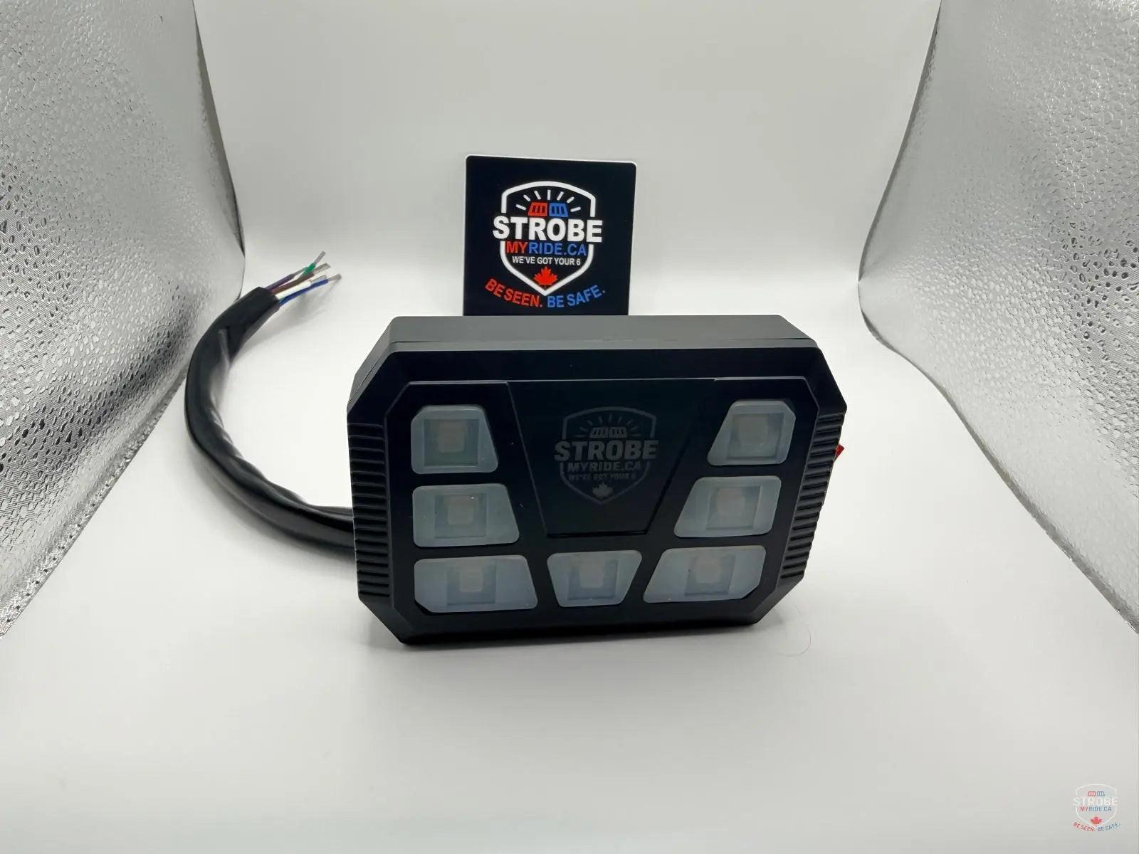
- The Patrol Switch is a purpose‑built LED control switch designed for emergency light circuits following exactly this wiring pattern.
Product spotlight: Patrol Switch for emergency light control
The Patrol Switch sits at the panel output stage of the wiring pattern covered above: switch input from the fused main feed, switch output to the emergency light circuit or its relay, and a ground return to the same bus as the rest of the panel. For anyone building or upgrading an emergency lighting panel, that means one dedicated switch position instead of adapting a generic rocker meant for something else. Full specifications and purchase details are available on the Patrol Switch product page, where Strobe My Ride lists the exact fitment and control details for the switch as sold.


