


Wire your Ram auxiliary switches correctly by using the factory switch as a low-current trigger to control a relay inside the Aux PDC, then feed your accessory from a separately fused battery source through the OEM upfitter connectors. Done this way, you preserve the factory load-management architecture and avoid overloading the switch outputs.
Quick parts list:
- 30A or 40A automotive relay (ISO mini or standard)
- Inline fuse holder or PDC fuse slot, sized to continuous draw
- Factory terminated pigtail from the Ram upfitter kit (1/4" blade terminals with seals)
- 10–12 AWG wire for battery feed runs; 14–16 AWG for relay coil control wiring
- Sealed butt connectors, heat shrink, dielectric grease
Two safety reminders before you touch anything:
- Disconnect the battery negative before inserting terminals or running wires.
- Size every fuse and relay to continuous draw, not peak flash current — the Aux PDC has a combined continuous amperage ceiling that is lower than the sum of its individual fuse ratings.
Key takeaways
Correct Ram aux switch wiring uses the factory LIN-bus trigger to actuate a relay, feeds the accessory from a separately fused battery source, and keeps combined continuous draw within the Aux PDC’s published limit.
| Point | Details |
|---|---|
| Aux switch is a trigger only | Never wire a high-current accessory directly to the switch output; always use a relay. |
| Fuse at the battery source | Place the inline fuse within 45 cm of the battery or PDC connection, sized to continuous draw. |
| Respect the PDC continuous limit | Combined continuous draw across all aux circuits must stay below the Aux PDC ceiling, not just the sum of fuse ratings. |
| Program EVIC before testing | Set power source, activation type, and last-state behaviour to match the accessory before the first live test. |
| Strobe My Ride modules | ZW-GM, ZW-FSD, and ZW-MFD2 are Canadian-sourced OEM-style controllers that integrate cleanly with this wiring approach. |
Table of Contents
- How does Ram’s factory auxiliary switch system actually work?
- Where are the Aux PDC and upfitter connectors, and what are the pinouts?
- Step-by-step Ram aux switch wiring procedure
- How do you size fuses and relays for the Aux PDC?
- How do you program aux switch behaviour in the EVIC?
- PTO switches and model-year differences to watch for
- How to test outputs and troubleshoot common faults
- Recommended parts and Strobe My Ride products for Canadian upfitters
- Canadian electrical safety and compliance for vehicle lighting
- Strobe My Ride: Canadian-sourced lighting and controllers for Ram upfitters
- Sources
How does Ram’s factory auxiliary switch system actually work?
Ram’s factory auxiliary switch system centres on the Upfitter Auxiliary Power Distribution Centre (Aux PDC), a dedicated relay-and-fuse box mounted in the engine bay. The dash-mounted aux switches do not carry accessory current themselves. They send low-current signals over a LIN bus to the Aux PDC, which then actuates relays inside the box. Those relay outputs are what you wire your accessories to.
Starting in 2019, Ram vehicles equipped with auxiliary switches have six aux switch positions (five programmable plus a PTO position on PTO-prep models). The relay outputs are exposed at two four-way connectors on the inboard side of the Aux PDC: one light grey (Upfitter_Aux_1) and one dark grey (Upfitter_Aux_2). Your upfitter kit includes wires pre-terminated with the correct 1/4" blade terminals and seals to click into those cavities.
Key architecture principle: The aux switch outputs are LIN-bus-driven triggers, not switched power feeds. Wiring a high-current accessory directly to a switch output — bypassing the relay — will damage the switch module and may void warranty. Always let the relay do the heavy lifting.
Using the factory-integrated switching approach also avoids interference with the vehicle’s CAN network and preserves OEM load management, which matters on modern Ram HD trucks where the PCM monitors electrical loads.
Programmable EVIC options for each switch:
- Power source: battery (always live) or ignition (only active with key on)
- Activation type: momentary (active only while pressed) or latching (toggles on/off)
- Last state: switch remembers its on/off state after a key cycle
The RAM Body Builder aux switches documentation provides the full programming flowchart and confirms all three parameters are configurable per switch through the EVIC instrument cluster.
Pro Tip: Set warning lights to “ignition” and “latching” so they cannot be left on accidentally with the engine off, draining the battery on a cold Canadian night.
Where are the Aux PDC and upfitter connectors, and what are the pinouts?
The Aux PDC sits on the driver’s side of the engine bay, mounted against the firewall. The two four-way upfitter connectors are on the inboard face of the Aux PDC, facing toward the engine centre. They are colour-coded: light grey for Upfitter_Aux_1 and dark grey for Upfitter_Aux_2.
The RAM Body Builder upfitter schematic (2017) includes connector pin labels, wire colour references, and per-circuit continuous current annotations. Always cross-reference your specific model year’s schematic before wiring, since cavity assignments can shift between years.
Typical pinout — Upfitter_Aux_1 (light grey, 4-way):
| Cavity | Aux Output | Typical Wire Colour |
|---|---|---|
| 1 | Aux 1 | Dark green |
| 2 | Aux 2 | Light green |
| 3 | Aux 3 | Grey |
| 4 | Ground reference | Black |
Typical pinout — Upfitter_Aux_2 (dark grey, 4-way):
Note: Wire colours and cavity assignments vary by model year. Confirm against your year-specific Ram upfitter schematic before inserting terminals.
From the upfitter schematic: Per-circuit continuous current limits are annotated directly on the diagrams. The installer is responsible for placing the correct fuse based on actual load — the PDC does not self-protect against undersized fusing.
Pro Tip: The upfitter kit’s pre-terminated wires are sealed at the connector end. Using aftermarket blade terminals instead risks breaking the cavity seal, which lets moisture in — a real problem in Canadian winters where road salt accelerates corrosion inside connectors.
Step-by-step Ram aux switch wiring procedure
This sequence covers a typical auxiliary lighting circuit: one aux switch controlling a relay, which switches a fused battery feed to the accessory.
- Disconnect the battery negative. Keys out, negative cable off, wait two minutes for capacitors to discharge.
- Identify your aux output. Decide which dash switch (Aux 1–6) you are using. Locate the matching cavity in Upfitter_Aux_1 or Upfitter_Aux_2 using the pinout table above and your model-year schematic.
- Remove the green protective plug from the target cavity on the upfitter connector. Take the factory-terminated wire from your upfitter kit and click it firmly into the cavity until it seats and the seal compresses.
- Install the relay. Mount a standard ISO mini relay in a dry, accessible location near the Aux PDC. Wire the relay coil positive (pin 86) to the terminated upfitter wire you just installed. Wire the relay coil negative (pin 85) to a clean chassis ground point — a factory ground stud near the Aux PDC works well.
- Run the battery feed. From the battery positive or a fused PDC location, run 10–12 AWG wire to relay pin 30 (common). Fuse this wire at the battery end or in the Aux PDC fuse slot — size the fuse to the accessory’s continuous draw, not its peak.
- Connect the accessory. Run 10–12 AWG wire from relay pin 87 (normally open) to the accessory positive input. Ground the accessory to a clean chassis point using a proper ring terminal on a factory ground stud.
- Verify wire routing. Keep all wiring away from exhaust components, moving parts, and sharp edges. Use split loom or conduit where wires pass through the firewall or along frame rails.
- Reconnect the battery and test. With everything connected, turn the key on, activate the aux switch, and confirm the relay clicks and the accessory operates.
Pro Tip: Use dielectric grease on any exterior splice or connector exposed to the elements. In Canadian climates, a splice without grease and heat shrink will corrode within one winter season, causing intermittent faults that are frustrating to trace.
For warning light controller wiring patterns that complement this relay approach, the warning light controller setup guide covers additional configuration options.
How do you size fuses and relays for the Aux PDC?
Getting fuse and relay sizing right is where most upfitter mistakes happen. The critical distinction is between a fuse’s rating and the Aux PDC’s continuous amperage limit. A 40A fuse in a slot does not mean you can draw 40A continuously from that circuit.
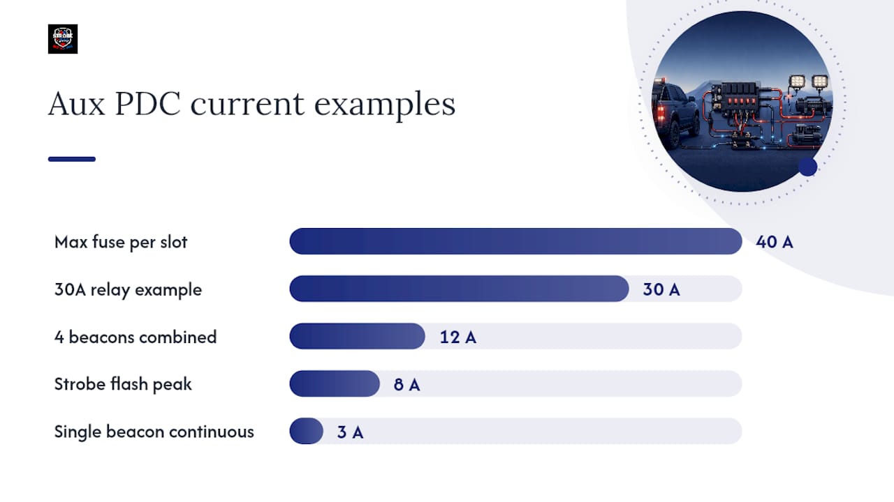
The 2019 Ram 2500/3500/4500/5500 Diesel Supplement confirms that the maximum fuse rating in any single Aux PDC location is 40A, and that the maximum allowable combined continuous amperage across all aux circuits is lower than the arithmetic sum of all installed fuse ratings. The installer is responsible for ensuring the combined continuous draw stays within that limit.
Worked example — four LED beacons:
Suppose you are wiring four amber LED beacons, each drawing 3A continuously at 12V.
- Combined continuous draw is the sum of each accessory’s continuous current
- Fuse selection per circuit should provide headroom above continuous draw
- Relay rating should be higher than continuous current for reliability
- Proper wire gauge selection depends on current and run length
Common mistake: Upfitters sometimes add up peak flash currents from strobe patterns rather than steady-state draw. A strobe beacon that peaks at 8A during a flash cycle may draw only 2.5A continuously. Sizing fuses and the combined PDC load against peak values wastes fuse capacity and can cause nuisance trips on the main feed.
Warning: Never exceed the Aux PDC’s maximum combined continuous amperage limit. Overloading the combined feed can trip the main supply fuse or damage wiring inside the PDC. Check the limit in your model-year supplement before adding circuits.
A 30A relay running a 3A circuit will last years; a 10A relay on the same circuit will eventually fail from contact wear in high-cycle applications like emergency flashers.*
For load calculations specific to surface-mount strobes, the surface-mount strobe lights fleet guide includes current draw references for common Canadian fleet lighting.
How do you program aux switch behaviour in the EVIC?
Program each aux switch from the instrument cluster EVIC menu following the Ram programming flowchart in the RAM Body Builder aux switches documentation.
Configurable options and recommended settings:
- Power source — Battery: use for accessories that must remain active regardless of ignition state (e.g., scene lighting that stays on after engine shutdown)
- Power source — Ignition: use for warning lights and strobes; prevents battery drain if a switch is left on
- Activation — Latching: recommended for lights; press once to activate, press again to deactivate
- Activation — Momentary: recommended for air horns, PTOs, or any device that should only be active while the button is held
- Last state — Enabled: switch returns to its previous on/off state after a key cycle; useful for work lights that should resume automatically
- Last state — Disabled: switch always starts in the off position after a key cycle; recommended for warning lights to prevent unintended activation
Programming steps:
- With the vehicle running or in accessory mode, navigate to the Settings menu in the EVIC display using the steering wheel controls.
- Select “Auxiliary Switches” from the menu list.
- Select the switch number you want to configure (Aux 1 through Aux 6).
- Set Power Source (Battery or Ignition), then Activation Type (Latching or Momentary), then Last State (On or Off).
- Confirm and exit. Test the switch to verify behaviour matches the setting.
Pro Tip: For fleet vehicles with multiple operators, document the PIN or EVIC configuration for each switch and store it with the vehicle’s service record. On VIN-dependent programming, some dealers can lock EVIC settings to prevent operators from accidentally reconfiguring switches in the field.
PTO switches and model-year differences to watch for
The most consequential gotcha in Ram aux switch wiring is the PTO position. On PTO-prep trucks, one aux switch position (typically Aux 5 or Aux 6, depending on model year) is dedicated to PTO engine management. This switch is hard-wired for PTO control and is not available for lighting or accessory use.
The Ram CC HD Upfitter Schematic MY23 documents the PTO relay, jumper wiring, and connector locations inside the Aux PDC. On PTO-prep vehicles, the Aux PDC contains a dedicated PTO relay and jumper provisions that differ from the standard six-relay layout.
Key model and year differences:
- 2019 and newer: generally six aux switch positions; PTO-prep models use one position for PTO, leaving five for accessories
- Pre-2019 models: fewer aux switch positions and different connector layouts; always consult the year-specific upfitter schematic
- PTO jumper placement in the Aux PDC changes the relay topology — do not assume a non-PTO schematic applies to a PTO-prep truck
Actions to avoid:
- Do not reassign the PTO switch for lighting or accessory control on a PTO-prep vehicle
- Do not remove or reposition PTO jumpers without consulting the Ram upfitter documentation for your specific model year
- Do not assume the Aux 5 or Aux 6 cavity is available without first verifying the vehicle’s build sheet and upfitter schematic
Pro Tip: Pull the vehicle’s window sticker or build sheet before starting any upfitter wiring. If “PTO Prep” appears in the option codes, download the PTO-specific upfitter schematic from the Ram Body Builder portal before touching the Aux PDC.
How to test outputs and troubleshoot common faults
A systematic test sequence saves hours of fault-chasing. Run through this before declaring the install complete.
Safe test sequence:
- Reconnect the battery negative last, after all wiring is complete and secured.
- With the key in accessory mode (engine off), activate each aux switch one at a time.
- Listen for the relay click inside the Aux PDC — audible confirmation that the LIN-bus trigger reached the relay coil.
- Use a multimeter set to DC volts: probe the upfitter connector cavity (accessory positive output) and chassis ground. You should read battery voltage (12.5–14.4V) when the switch is on.
- Verify the accessory ground with a continuity check from the accessory ground terminal to a known chassis ground stud.
- Start the engine and retest all circuits under charge voltage.
Troubleshooting common faults:
| Symptom | Likely cause | Quick test | Fix |
|---|---|---|---|
| Switch activates but relay does not click | No aux trigger at connector cavity | Measure voltage at cavity with switch on; expect 12V | Check EVIC programming; verify terminal is seated in cavity |
| Relay clicks but accessory does not run | Open fuse or broken battery feed | Check inline fuse; measure voltage at relay pin 87 | Replace fuse; repair open in battery feed wire |
| Accessory runs but dims or flickers | Poor chassis ground | Measure voltage drop across ground connection | Clean and retighten ground ring terminal |
| Accessory runs continuously regardless of switch | Relay contacts welded or wired to pin 87A (NC) | Swap relay; verify wiring to pin 87 (NO) | Replace relay; correct wiring |
| EVIC does not show aux switch menu | Switch option not enabled or incorrect trim level | Confirm vehicle has factory aux switch option | Consult dealer for EVIC configuration |
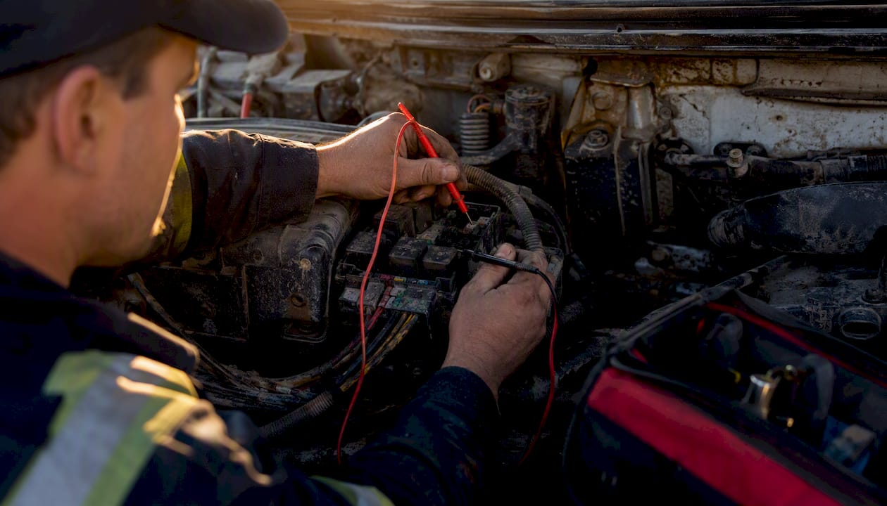
Pro Tip: Always use fused temporary test leads when probing live circuits during diagnosis. A bare probe tip that slips and contacts a ground can short a battery feed and damage wiring or the Aux PDC in seconds.
Recommended parts and Strobe My Ride products for Canadian upfitters
A clean Ram aux switch installation needs the right hardware from the start. Here is what to have on hand before you begin.
Hardware list:
- 30A or 40A ISO mini automotive relays (one per aux circuit)
- Inline fuse holders (ATC/ATO) or Aux PDC fuse slots, with fuses sized to continuous draw
- 10–12 AWG primary wire for battery feed runs
- 14–16 AWG primary wire for relay coil and control circuits
- Sealed butt connectors (heat-shrink lined) for any mid-run splices
- Ring terminals for chassis ground connections
- Split loom conduit and cable ties for harness management
- Dielectric grease for exterior connectors and splices
For Canadian fleet operators who want OEM-style flash control integrated with their Ram aux switch wiring, Strobe My Ride offers three purpose-built modules:
- The ZW-GM flasher controller is designed for OEM-style light control and suits installers who need a clean, plug-and-play interface compatible with GM-style wiring architectures — useful when your fleet includes mixed makes.
- The ZW-FSD controller handles dedicated flash patterns and is well suited to fleet deployments where consistent, repeatable flash sequences are required across multiple vehicles.
- The ZW-MFD2 OBD2 Flash Module connects via OBD2 and enables OEM-style flash behaviour without cutting into the factory harness — a practical choice when you need to retain OEM behaviours while adding custom flash patterns.
Choosing OEM-style flasher modules reduces harness complexity, preserves the factory electrical architecture, and simplifies troubleshooting down the road. For more background on why Canadian fleets are moving toward OEM-compatible controllers, the OEM flasher modules guide covers the compatibility and compliance reasoning in detail.
Canadian electrical safety and compliance for vehicle lighting
Electrical safety rules for every install:
- Disconnect the battery negative before any wiring work; reconnect it last.
- Use wire gauge matched to the circuit’s continuous amperage and run length — undersized wire generates heat and is a fire risk.
- Fuse every battery feed at the source, within 45 cm of the battery or PDC connection point.
- Route all wiring away from exhaust components, brake lines, and moving parts; use grommets where wires pass through sheet metal.
- Secure harnesses with cable ties every 30–45 cm; avoid zip-tying to fuel or brake lines.
Canadian regulatory context:
Warning light colours, activation requirements, and permitted vehicle classes are governed by provincial legislation and, for federally regulated carriers, by Transport Canada under the Motor Vehicle Safety Act. The rules vary by province and by vehicle use. Amber lighting for construction, towing, and slow-moving vehicles is addressed in provincial highway traffic acts (for example, Ontario’s Highway Traffic Act, Alberta’s Traffic Safety Act), and municipalities may impose additional restrictions on when and where warning lights may be activated.
Important: No warning light product can be declared legal or approved for all uses across Canada. Permitted colours, flash patterns, and mounting positions depend on the vehicle class, the province, and the specific use case. Verify requirements with your provincial ministry of transportation and, where applicable, your municipality before installing any warning device on a public-road vehicle.
For amber lighting guidance specific to Canadian professional vehicles, the amber strobe lights guide outlines provincial considerations and product options.
Pro Tip: If you are upfitting a vehicle for a municipality or regulated carrier in Canada, request written confirmation of the permitted lighting specification from the authority having jurisdiction before purchasing equipment. Requirements can differ between a city’s public works department and a provincial ministry — getting it in writing protects both the installer and the fleet operator.
Strobe My Ride: Canadian-sourced lighting and controllers for Ram upfitters
Canadian fleet operators and professional upfitters working with Ram auxiliary switch wiring need parts that arrive fast, carry real technical support, and are specified for Canadian conditions. Strobe My Ride supplies exactly that: OEM-compatible flasher modules, LED warning lights, and upfitting hardware shipped from Canada, backed by industry warranties and a team that understands vocational vehicle builds.
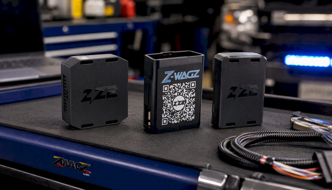
The ZW-GM, ZW-FSD, and ZW-MFD2 OBD2 Flash Module are stocked for Canadian buyers and pair directly with the relay-based wiring approach covered in this guide. Whether you are outfitting a single tow truck or specifying lighting for a municipal fleet, Strobe My Ride’s product range covers the full install: from the relay and fuse hardware through to the warning light itself. Browse the Strobe My Ride Patrol Series collection or contact the team directly to confirm the right module for your Ram model year and accessory load.
Sources
- RAM Trucks — Body Builder image (Auxiliary switches, 2019)
- 2019 RAM 2500/3500/4500/5500 6.7 Diesel Supplement
- RAM Body Builder — Aux switches documentation (2015)


