


Wired sync is the right call for coordinating heads on a single vehicle, while GPS/time-reference modules or managed on-scene sync systems handle multi-vehicle fleets more reliably. Most professional-grade systems support syncing up to 14 connected light heads on one circuit, though you should always verify that limit against the specific product manual. The sections below walk through wiring, wireless and GPS approaches, testing, and a rollout checklist for scaling this across a fleet.
TL;DR:
- Wired synchronization is most reliable for single vehicles with multiple heads, but it is limited to about 14 heads per circuit, depending on the product.
- GPS or time-reference systems are essential for coordinating flash patterns across multiple vehicles and support automatic on-scene pattern adjustments.
- Proper installation requires testing sync before final fastening to prevent drift or malfunction caused by grounding issues or loose connections during vibration.
- Bluetooth Low Energy timestamp systems provide a flexible, accurate alternative for fleets where wiring is impractical, maintaining sub-10 millisecond accuracy with correct setup.
- Standardizing patterns across a fleet should involve pilot testing on one vehicle for at least a week and documenting configurations to ensure consistent performance during scaling.
What synchronization methods exist and when each fits
Synchronizing LED strobes means locking the flash timing of multiple heads or vehicles so they read as one coordinated signal instead of a chaotic scatter of light. Three approaches dominate the fleet lighting world, and each solves a different problem.
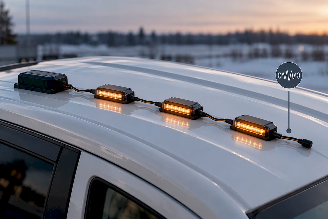
Wired sync relies on a dedicated sync wire running between heads, with one unit typically acting as master and the rest following as slaves. It is the most dependable method for a single vehicle because the timing signal travels over copper, not air, so there is no interference to manage and no pairing process to repeat. This is the default approach for most light bars, hideaways and surface-mount strobes installed on one truck or trailer.
GPS/time-reference sync solves a different problem: how do you align flash patterns across several vehicles that aren’t wired together? Rather than broadcasting timing signals vehicle to vehicle, these systems use a shared time reference (commonly GPS atomic-clock time) so each vehicle’s controller calculates the correct flash phase independently. This avoids the cumulative drift that plagues simple radio-timing schemes and supports “on-scene” modes where multiple vehicles automatically shift to a slower, shared pattern once they arrive at a location.
Wireless timestamp approaches, including Bluetooth Low Energy (BLE) master-clock designs, exchange timing data between devices and resync periodically. Properly implemented, these can hold sub-5 to 10 millisecond accuracy, which is tight enough for flash periods measured in hundreds of milliseconds.
Practical planning points:
- Wired sync: best for one vehicle, multiple heads, zero interference risk.
- GPS/time reference: best for fleets, convoys and multi-vehicle scenes.
- BLE timestamp: viable for custom retrofits where a manufacturer sync module isn’t an option.
- Head-count limits vary by product line, so confirm the manual before designing a multi-head circuit.
How wired synchronization works on one vehicle
Most head-based strobe systems use a sync wire and an election process where one head (or the controller) becomes master and the rest fall in line as slaves. On self-contained heads, that sync wire daisy-chains from unit to unit. On controller-driven setups, the controller issues the timing reference and each head simply follows it. Either way, unused sync wire connections on heads not participating in the chain need to be capped, since a floating sync line is a common source of erratic flash behaviour.
The faults that show up most often during install are electrical, not electronic. Poor grounds, voltage drop across long runs, and grounds daisy-chained through the vehicle body all create small differentials in supply voltage between heads. That shows up as heads that flash slightly out of step, dim unevenly, or fail to lock into sync at all. A practical wiring guide for vehicle strobe installs recommends dedicated fused circuits, relays for higher current draw, weatherproof connectors and separate ground returns as the baseline fix for most of these issues.
A repeatable testing sequence catches problems before the heads are permanently mounted:
- Power each head individually and confirm it flashes correctly on its own.
- Connect the sync wire chain and power the full circuit.
- Press and hold the momentary sync switch (or trigger the manufacturer’s sync command) until all heads lock to the same pattern.
- Power-cycle the whole circuit and confirm the heads re-sync automatically or re-trigger sync per the manual’s instructions.
- Recheck sync after final fastening, since vibration during mounting can shift a marginal connection.
Manufacturer manuals for surface-mount strobe series describe this exact momentary-sync routine, and some series support up to 14 heads on a single sync chain, though that ceiling depends entirely on the product line.
Pro Tip: Test sync before you commit to final fastening, not after. A head that reads perfectly on the bench can drift out of sync once it’s screwed down and the ground path changes slightly under vibration.
Every product family handles the sync command a little differently, so treat the steps above as a general framework and confirm the exact procedure against the specific product manual before wiring a new SKU into an existing fleet standard.
How GPS and wireless timing solve multi-vehicle sync
Wired sync stops working the moment two vehicles need to flash in step, because there’s no wire to run between them. That’s the gap GPS/time-reference systems close. Manufacturers increasingly use a shared time reference like GPS atomic-clock timing rather than direct radio timing between vehicles, because a shared clock reference doesn’t accumulate drift the way peer-to-peer RF timing does over minutes or hours.
This underpins a feature worth understanding for any fleet running multiple vehicles at one scene: automatic on-scene sync. Systems built around this concept detect arrival at a location and switch the group to a common, typically slower, flash pattern, which cuts down on the glare and visual noise created by several vehicles flashing on independent timing. Unsynchronized lighting at a busy scene isn’t just visually messy. It adds to responder stress and makes it harder for approaching drivers to read the scene at a glance.
For fleets building custom retrofits rather than buying a manufacturer’s managed sync module, a BLE timestamp master-clock approach is a workable alternative. One device establishes itself as the timing master, broadcasts a timestamp, and the rest of the fleet’s controllers calculate their flash phase from that reference, resyncing on a regular interval to correct for clock drift between refreshes.
A few operational notes worth planning around:
- Initial GPS lock typically takes longer at startup than resync intervals thereafter.
- Holdover behaviour matters: a module needs to hold reasonably accurate timing for short GPS dropouts (tunnels, dense urban canyons) without visibly drifting.
- Resyncing at pattern boundaries, rather than mid flash, tolerates normal crystal drift without producing a visible stutter.
- Well-designed BLE timestamp systems can hold accuracy in the 5 to 10 millisecond range, which is comfortably tight for flash periods running hundreds of milliseconds long.
Some hardware, such as gangable synchronization control modules, takes a wired-zone approach to the same problem, using two-wire connections to synchronize strobes and horns across a zone rather than relying on GPS at all. Which route fits depends on whether the vehicles in question are ever wired together or always operating independently.
Rollout checklist for standardizing sync across a fleet
Choosing the sync method comes down to how the vehicles actually work. A single service truck with three or four heads is a wired-sync job every time. A snow-removal fleet running convoys, or a group of vocational vehicles working the same job site, needs the GPS/time or managed-module approach because there’s no wire to run between trucks.
Once the method is chosen, standardize before you scale. Most fleets do well with two flash pattern profiles: a higher-intensity travel pattern for driving, and a slower, lower-intensity pattern for on-scene work that reduces glare for other vehicles and reduces strain on the crew working nearby. Keep a configuration sheet per vehicle listing the pattern assigned, the SKU installed, and the controller settings used, so the next technician working on that truck isn’t guessing.
Before scaling any configuration across the fleet, pilot it on one vehicle first:
- Check each head individually, confirming flash pattern and mounting position.
- Verify pattern timing against the configuration sheet, not by eye alone.
- Power-cycle the vehicle and confirm sync recovers automatically or per the documented manual procedure.
- Disconnect and reconnect the battery to confirm the controller and heads recover to the correct pattern.
- Recheck the flash rate against the expected setting, since incorrect flash rate is one of the most common inspection failure points upfitters run into.
Assign a specific person to sign off on each pilot install, and keep that sign-off documented alongside the SKU, wiring harness details, and controller program settings. It saves time months later when a second technician needs to replicate the same build.
Battery runtime is worth factoring in before you standardize a pattern fleet-wide, particularly if a scene-mode pattern runs strobes continuously during long stationary jobs. Strobe My Ride’s runtime math for battery drain calculations walks through how to estimate draw so a pattern choice doesn’t leave a vehicle with a dead battery at shift change.
Pro Tip: Pilot the new configuration on one vehicle for a full week of normal use before rolling it out fleet-wide. Bench testing catches wiring faults, but only a week of real driving and scene work catches the intermittent ones.
For a more detailed walkthrough of standardizing patterns across an entire fleet, Strobe My Ride’s guide to rolling out consistent light patterns covers the documentation and sign-off process in more depth.
Strobe My Ride resources for sync projects
Fleet sync projects commonly use surface-mount strobes, hideaway heads, and integrated strobe work lights, available from Canadian suppliers and shipped nationwide. Surface-mount and hideaway heads are the most common building blocks for wired sync chains on a single vehicle, while integrated strobe work lights suit crews who need combined task lighting and warning function without running two separate systems.
Sync wiring and timing behaviour varies by SKU, so check the individual product page before finalizing a fleet standard, and reach out to Strobe My Ride’s technical support team for SKU verification or a fleet quote before ordering in volume. Some fleets running convoy or multi-vehicle configurations, similar in coordination principle to the way commercial vehicle fleets manage multiple units on the road together, benefit from confirming sync behaviour across an entire order before committing to a fleet-wide rollout.
Get the right strobes for a synchronized install
Choosing a local supplier with stocked inventory helps avoid long cross-border shipping delays while pilot vehicles await installation. If a wired sync chain is the plan, the Signal SM Flex flexible surface mount LED strobe and the Patrol Hideaway LED hideaway strobe are both built as sync-chain heads suited to single-vehicle installs. For crews that need task lighting and warning function combined, the Signal WL N work light with integrated strobe covers both jobs from one fixture.
Before ordering across a fleet, confirm SKU-specific sync behaviour with the product technical support team, or request a fleet quote for volume pricing. If you’re still comparing head types and configurations, browse the full collection to see what’s currently in stock.
Sources
FAQ
How many LED strobe heads can I sync together?
It depends entirely on the product line, but many professional-grade systems support syncing up to 14 connected heads on a single circuit. Always confirm the actual limit in the specific product manual before designing a multi-head chain.
What’s the difference between wired sync and GPS sync?
Wired sync uses a physical sync wire between heads on one vehicle and is the most reliable option when a wire connection is possible. GPS/time-reference sync uses a shared clock reference instead of a physical connection, which is why manufacturers favour it for multi-vehicle and fleet-wide coordination.
Can I sync strobes across multiple vehicles without GPS?
Yes, through a BLE timestamp master-clock approach, where one controller broadcasts a timing reference and others resync periodically. This can hold sub-10 millisecond accuracy with a well-designed resync interval, though it takes more setup than a manufacturer’s managed sync module.
Why do my strobes go out of sync after a power cycle?
Poor grounds, voltage drop, or a floating (uncapped) sync wire are the most common causes. Run through the manufacturer’s sync procedure again after any battery disconnect or power interruption to confirm the heads re-lock correctly.
Does Strobe My Ride sell strobes ready for synchronized fleet installs?
Strobe My Ride stocks surface-mount strobes, hideaway heads and integrated strobe work lights suited to sync-chain installs, including the Signal SM Flex and Patrol Hideaway. Pricing for fleet orders is available on request through the technical support team.


