


For most vehicle and marine LED strobes, the core wiring is straightforward: red connects to fused +12V or +24V, black goes to chassis ground, and the yellow or white trigger wire connects to a switched or momentary 12V source to select flash patterns or synchronise multiple heads. Many professional-grade strobes accept both 12V and 24V, so confirm your supply voltage before you start. The trigger wire can be wired to a momentary push-button (for pattern cycling) or a latching switch (for steady on/off control), depending on your controller.
Before touching a single wire, disconnect the battery and fit an inline fuse on the positive lead at the first point of connection near the battery terminal. Those two steps prevent the most common installation failures.
- Red wire: fused positive supply (+12V or +24V)
- Black wire: chassis negative/ground
- Yellow or white wire: trigger, pattern select, or sync input
- Disconnect battery before starting; fuse the positive at the battery
Key takeaways
Correct strobe light wiring requires a fused positive at the battery, a solid metal-to-metal chassis ground, and a correctly identified trigger wire before you connect power to any head.
| Point | Details |
|---|---|
| Fuse at the battery | Fit an inline fuse on the positive wire as close to the battery terminal as practical, sized to the wire’s ampacity. |
| Solid chassis ground | Remove paint to bare metal at the ground point; a poor ground causes flickering, dim output, and radio interference. |
| Trigger wire behaviour | Confirm whether your trigger wire needs a momentary pulse (pattern cycle) or a 3–5 second hold (sync lock) before wiring. |
| Common source for sync | All heads in a multi-head setup must share the same positive feed and ground to prevent sync drift over time. |
| Strobe My Ride plug-and-play | The Patrol Hideaway, Fleet Hide Duo, and Patrol Hideaway 360 Duo include harnesses and diagrams for faster, safer Canadian installs. |
Table of Contents
- What do the wire colours on a strobe light actually mean?
- How to wire a single 3-wire strobe: step-by-step
- How do you wire multiple strobe heads and keep them synchronised?
- Momentary vs latching switches: which do you need?
- Fuse sizing, wire gauge, and protecting your wiring
- Marine wiring: what you need to do differently
- Canadian legal and safety checklist before you install
- Strobe My Ride: plug-and-play options with Canadian support
- Sources
What do the wire colours on a strobe light actually mean?
Standard colour coding on professional LED strobes follows a consistent pattern, though manufacturer wiring diagrams should always be your first reference before assuming any wire’s function.
| Wire Colour | Function | Notes |
|---|---|---|
| Red | Positive supply (+V) | Connect via inline fuse; 15 A minimum example |
| Black | Chassis ground/negative | Metal-to-metal contact required |
| Yellow | Trigger / pattern select | Low current; 22 AWG acceptable |
| White | Trigger / sync (alt.) | Same function as yellow on some models |
| Violet | High/low power select | Present on multi-power models |
| Green / Blue | Additional pattern wires | Low current; varies by manufacturer |
The trigger wire works differently depending on how you apply voltage. A momentary pulse (touching 12V briefly) typically steps through flash patterns. Holding the trigger wire at 12V for 3–5 seconds locks in synchronisation across multiple heads or programs a specific pattern. Some controllers require a steady positive to exit a low-current shutdown mode, so if a unit appears dead after installation, check whether the trigger wire is receiving voltage.
Manufacturers do deviate from this standard. Violet wires for high/low power selection and separate green or blue wires for pattern cycling appear on multi-function heads. Never assume colour function on an unfamiliar harness.
Pro Tip: Before cutting or crimping any wire on an unknown harness, use a multimeter set to DC voltage and probe each wire with the unit powered but not yet mounted. A reading of 0V on the trigger wire confirms it is a control input, not a live power wire. A test lamp works too, but a multimeter gives you the exact voltage and rules out polarity surprises before you commit to a long cable run.
How to wire a single 3-wire strobe: step-by-step
Tools and materials
- Multimeter (DC voltage and continuity)
- Wire strippers and crimping tool
- Inline fuse holder and appropriate fuse (15 A is a common starting point)
- Heatshrink tubing and solderless crimp connectors
- Ring terminals for ground connections
- Correct wire gauge for your run length (see Section 6)
- Self-tapping screws or bolts for mounting
- Silicone sealant or split-loom conduit for exterior cable runs
- Grommets for any panel penetrations
Preparation
- Read the manufacturer’s wiring diagram completely before cutting anything.
- Choose your mounting location and confirm the surface is solid enough to hold the strobe under vibration.
- Plan your cable route from the battery to the head, noting any metal panel penetrations.
- Disconnect the negative battery terminal.
Wiring sequence
- Run the red positive wire from the battery positive terminal through an inline fuse holder, then to your on/off switch or controller input.
- Run the switch or controller output to the strobe’s red wire.
- Run the black wire to a clean chassis ground point. Remove paint down to bare metal at the grounding location and use a ring terminal torqued firmly to the chassis bolt.
- Connect the yellow or white trigger wire to your switch output or controller trigger terminal. If pattern selection is not needed, some units allow this wire to be left unconnected or tied to the positive supply for a fixed pattern — confirm in the diagram.
- Route all wiring through grommets at any metal panel penetrations. Secure cables with cable ties every 30–45 cm to prevent chafing.
- Reconnect the battery and test on the bench before final mounting.
A poor chassis ground is the single most common cause of dim output, flickering, or radio interference. Bare metal contact is not optional. Matching your power supply voltage and amperage to the fixture and verifying the wiring diagram before final installation are the two steps professionals skip at their peril.
Verify polarity on pre-crimped connectors before running long cable runs. Reversed pins at a junction cause significant rework if not caught at the bench test stage.
How do you wire multiple strobe heads and keep them synchronised?
Running two or more heads requires a common power and ground source. Separate power blocks cause sync drift over time because the heads cannot share a timing reference. The standard topology looks like this:
- Single positive feed from the battery, through one inline fuse, to a distribution point
- Parallel red wires from the distribution point to each head
- All black wires tied to the same chassis ground location (or a common ground bus)
- Sync/trigger wires joined together at a common bus, then connected to the controller or switch
Synchronisation sequence
Synchronisation instructions from Custer Products describe the standard workflow clearly:
- Power on each head individually and set every head to the same flash pattern.
- Power down all heads.
- Connect all sync/trigger wires together at the common bus.
- Power on all heads simultaneously.
- Apply 12V to the sync bus and hold for 3–5 seconds to lock the pattern across all heads.
If any head was set to a different pattern before the sync wires were tied together, the sequence will not lock correctly. Reprogram all heads to the same pattern before attempting the sync hold again.
Pro Tip: On long sync wire runs (over 3 metres), use twisted-pair wire or keep the sync run as short as practical. Unshielded sync wires running parallel to power cables can pick up electrical noise and cause timing drift, especially in vehicles with alternators or inverters nearby.
Troubleshooting unsynchronised heads
- Confirm all heads share the same positive feed and ground point
- Test trigger wire continuity from the controller to each head with a multimeter
- Verify each head was set to the same pattern before the sync wires were joined
- Check that the sync hold time reached the full 3–5 seconds
- Inspect ground connections for corrosion or loose fasteners
| Symptom | Likely cause | Fix |
|---|---|---|
| Heads flash out of phase | Different patterns set before sync | Reprogram all heads, repeat sync |
| One head not flashing | Open ground or trigger wire | Test continuity; re-terminate |
| Sync drifts after a few minutes | Separate power sources | Tie all reds to one feed |
| All heads dead | Blown fuse or no trigger voltage | Check fuse; verify trigger input |
Momentary vs latching switches: which do you need?
The choice between a momentary and latching switch depends on what you are controlling.
A latching (on/off) switch holds the circuit closed until you press it again. Use this for the main power feed to the strobe’s red wire. A standard rocker or toggle switch works well here.
A momentary (push-to-make) switch closes the circuit only while held. Use this for the trigger or sync wire when you want to cycle through flash patterns or initiate a sync sequence. Releasing the button returns the trigger wire to 0V.
Wiring examples
- Simple on/off control: Battery positive → inline fuse → latching rocker switch → strobe red wire. Black to chassis ground. Trigger wire tied to positive supply for a fixed pattern (confirm in diagram).
- Pattern cycling: Battery positive → inline fuse → strobe red wire (always live when ignition is on). Trigger wire → momentary push-button → 12V source. Each press steps through patterns.
- Multi-pattern controller: Battery positive → inline fuse → controller power input. Controller outputs to each head’s red wire. Controller trigger output to sync bus. Controller pattern select to rotary or multi-position switch.
The trigger and pattern wires carry very low current, typically well under 1 A, so 22 AWG wire is sufficient for those runs. The power wire to the head itself carries the full load current and must be sized accordingly. When heads draw more than 5 A combined, use a relay so the vehicle switch only carries the relay coil current, not the full head load.
Pro Tip: Pre-wired switch harnesses with built-in relays simplify installation and protect your dash switches from overload. If you are wiring a hideaway strobe install into a work truck, a relay-based harness keeps the control wiring clean and the switch rated for years of daily use.
When mounting controllers, choose a dry interior location away from heat sources. Controllers that are not rated waterproof will fail in marine environments unless housed in a sealed enclosure with an appropriate IP rating.
Fuse sizing, wire gauge, and protecting your wiring
Fuse the positive wire at the battery terminal, as close to the battery as practical. The fuse protects the wire, not just the device. Size it to the wire’s ampacity, not simply the device’s draw.
Wire gauge by run length
Installation documentation confirms that control wires (yellow, green, blue) can run at 22 AWG because they carry negligible current, while power wires must be sized to the run length and total amperage.
Calculating fuse size
Divide total wattage by supply voltage to get amperage. A 90 W strobe power supply on a 12V system draws 7.5 A. Never size a fuse above the wire’s ampacity.
Note that when a 90 W supply feeds two heads, output divides between them (45 W per head). Do not exceed the rated wattage per head outlet.
Additional protection practices:
- Route power wiring away from fuel lines and exhaust components
- Use grommets at every metal panel penetration to prevent chafing
- Apply heatshrink over all crimp connections
- Secure wiring every 30–45 cm with cable ties
- If a strobe appears dim, measure voltage at the head under load; a drop of more than 0.5V suggests undersized wire or a poor ground
For fleet operators managing electrical safety across multiple vehicles, a documented wiring standard for each vehicle type reduces rework and speeds up troubleshooting.
Marine wiring: what you need to do differently
Boats present a harsher environment than vehicles. Salt air, bilge moisture, vibration, and the risk of galvanic corrosion mean that standard automotive wiring practices are not sufficient.
- Use marine-grade tinned copper wire throughout. Tinned conductors resist corrosion far better than bare copper in humid environments.
- Use sealed, heat-shrink crimp connectors with adhesive-lined heatshrink. Standard open-barrel crimps corrode quickly in marine conditions.
- Apply dielectric grease to every connection before sealing.
- Provide strain relief at every connector and at any point where the cable changes direction.
- Route cables away from bilge areas. Standing water and strobe wiring do not coexist.
- Secure cables with UV-resistant cable ties or stainless steel clamps.
Grounding on a boat requires extra care. Avoid using the engine block as a ground point if it shows any corrosion. Use the vessel’s dedicated DC negative bus and confirm it is properly bonded. If the vessel has shore power, consult the electrical plan before connecting any new 12V ground to avoid creating a galvanic corrosion path. Zinc anodes protect the hull, not your wiring.
For controllers and power supplies, treat any unit without an explicit waterproof rating as non-waterproof. Mounting a control box in an exposed cockpit locker is a reliable way to generate intermittent failures within one season. Weatherproof strobe options exist specifically for exposed mounting situations.
Pro Tip: Mount the control box inside a dry interior locker and run only sealed exterior cables with marine-grade cable glands through the hull or deck. This single practice eliminates the majority of moisture-related failures reported by marine installers.
Canadian legal and safety checklist before you install
Strobe light wiring on a Canadian vehicle is not purely a technical exercise. The Motor Vehicle Safety Regulations (C.R.C., c. 1038) govern vehicle lighting at the federal level, and TSD 108 contains the technical details on lamp activation, switching, and photometric performance that determine whether a given flash pattern or mounting location is acceptable for a specific vehicle class.
Emergency service warning lights (police, fire, ambulance) operate under different rules than aftermarket warning lights fitted to work vehicles such as tow trucks, snow plows, or pilot cars. Permitted colours, mounting locations, and flash behaviours vary by vehicle class and by province. Ontario, Alberta, and British Columbia each have their own highway traffic legislation that governs which vehicles may display which colours. What is permitted for a volunteer firefighter’s personal vehicle in one province may not be permitted in another.
Compliance checklist:
- Identify your vehicle class and intended use before selecting any strobe colour or mounting location
- Check permitted colours for your province and vehicle type (amber is the most broadly permitted for non-emergency work vehicles)
- Confirm flash pattern and activation rules under TSD 108 for your vehicle class
- Keep records of the strobe’s intended use and installation details
- Consult Transport Canada or your provincial ministry of transportation page for your specific situation
Safety checklist before energising:
- Battery disconnected before any wiring work
- Inline fuse fitted at the battery positive terminal
- All ground connections made to bare metal
- Wiring secured and protected through grommets at panel penetrations
- Polarity verified at the head connector before power-up
- Bench test completed with a multimeter before final mounting
Pro Tip: If you are unsure whether a specific strobe colour or flash pattern is permitted for your vehicle class in your province, treat it as a point for manual review and contact your provincial ministry of transportation directly. A vehicle strobe lights guide for Canadian professionals can help you frame the right questions before you call.
This article provides general technical information. Confirm current regulations with Transport Canada, your provincial ministry of transportation, or a qualified professional before installation.
Strobe My Ride: plug-and-play options with Canadian support
Getting the wiring right is easier when the harness is already designed for your vehicle. Strobe My Ride supplies plug-and-play hideaway and patrol series strobes built for Canadian work vehicles and fleet applications, with wiring diagrams, harness compatibility details, and Canadian warranty coverage included.
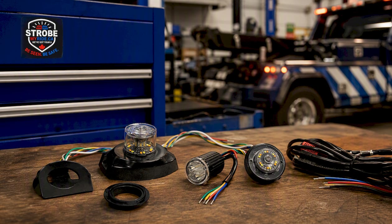
Three products worth knowing for a quicker hideaway strobe install:
The Patrol Hideaway LED Hideaway Strobe is a three-head plug-and-play system designed for tow trucks, roadside assistance, and fleet vehicles. The harness follows the standard red/black/trigger colour scheme, and the product page includes the wiring diagram you need before you start.
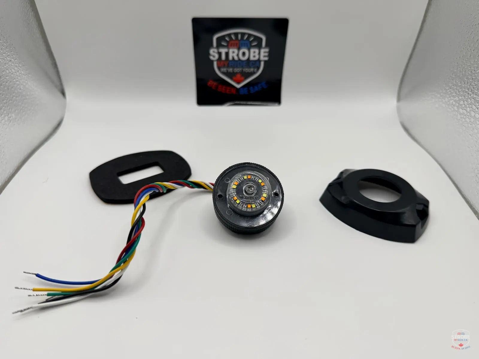
The Fleet Hide Duo is a compact dual-head option suited to fleet vehicles where space is limited. Its smaller footprint simplifies routing and reduces the total wire run length, which keeps fuse sizing and gauge selection straightforward.
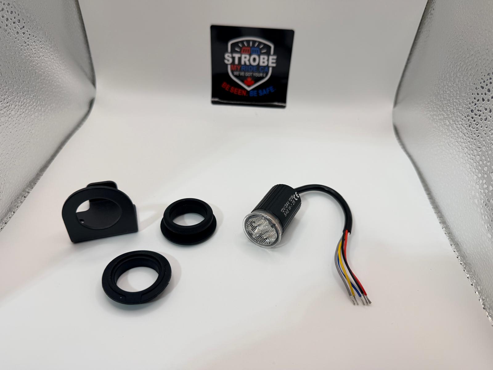
The Patrol Hideaway 360 Duo delivers 360° coverage from a hideaway-style mount, useful when visibility from all angles is a priority and a surface-mount light bar is not practical.
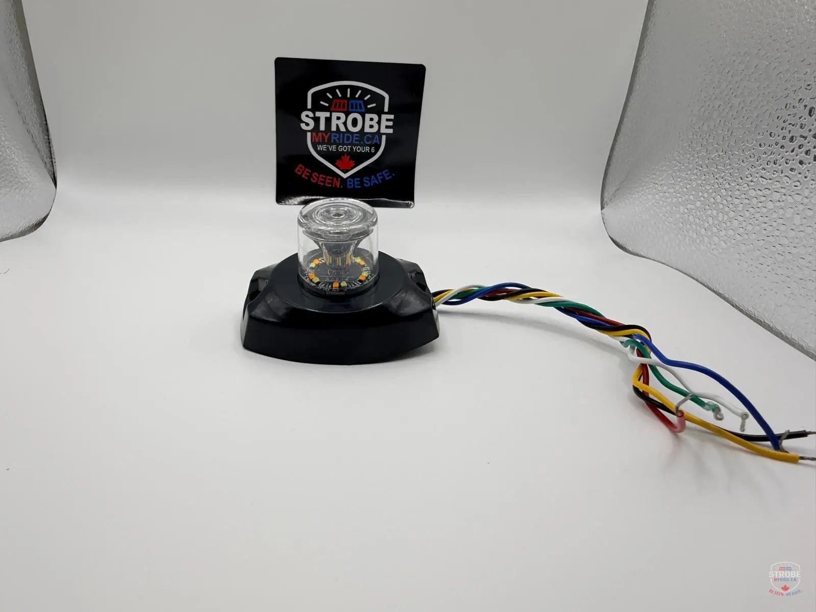
All three ship from Canada with technical support available for installation questions. If you need a wiring diagram, harness compatibility confirmation, or help sizing a fuse for your specific setup, contact Strobe My Ride directly before you start the job.
Sources
- INSTALL-7414-0090-00 (strobe power supply install and wiring diagrams)
- Motor Vehicle Safety Regulations (C.R.C., c. 1038)
- STR63AWF & STR63AF synchronising instructions — Custer Products
- Wiring LED strobe lights guide | KIMU
Recommended
- Vehicle strobe lights for Canadian professionals: 2026 guide | Strobe My Ride – Strobe My Ride
- Surface mount strobe lights: a Canadian fleet guide | Strobe My Ride – Strobe My Ride
- Construction truck strobe lights: Canada-ready buying guide | Strobe My Ride – Strobe My Ride
- Surface Mount Strobe Lights That Work | Strobe My Ride – Strobe My Ride


